
The technology
The liquid piston
Isothermal compression is the most efficient way to turn shaft work into stored gas energy, and back. The hard part has never been knowing that — it has been building a machine that can do it at scale and economics. EIC does it with a column of liquid.
Removing heat is not losing energy
True isothermal compression and expansion is the most efficient possible way to transfer shaft work into the potential energy of a gas and back. At first glance, losing heat looks like deliberately throwing energy away. The fact is that getting the heat out of the way real-time during compression makes the required energy lower to get to any pressure.
For energy storage and retrieval applications, the resolution is in where you draw the system boundary. So long as heat can move back into the process at the rate needed to hold temperature steady, the thermodynamic system is not the compression vessel alone. It is the compression vessel, the storage vessel and the atmosphere, together. The heat was never removed from that system. It is parked, and it is recoverable.
What we are really doing is using the atmosphere as an infinite heat sink during compression, so that incoming energy is not spent raising the gas temperature and fighting the pressure rise that comes with it — and then using that same atmosphere as an infinite heat source during expansion. The closer a real machine gets to holding temperature constant, the closer it gets to the theoretical maximum.
Why adiabatic wins on paper and loses in the field
Run the comparison in theory and adiabatic compression looks fine. No heat leaves, the gas gets hot, and if that temperature rise could be held indefinitely the heat energy would still be there to recover alongside the pressure. On paper, no disadvantage.
Reality intervenes at the storage vessel. That heat escapes over time, and the total energy in the stored gas falls with it. The energy you put in is not all there when you come back for it. In the adiabatic case the honest system boundary is just the compression and storage vessels, because heat that has leaked away cannot be pulled back quickly — it is genuinely outside the system now.
That leaves two options: store the heat and reintroduce it later, or add heat by burning something. Storing low-grade heat for long periods is difficult, and burning fossil fuel to recover your renewable storage rather defeats the purpose. Isothermal compression produces cool gas. This is the real link between isothermal compression and long duration storage: without it, how long you can usefully store energy is capped by how long you can hold onto heat.
Where the energy actually goes
Dissipating the heat of compression in real time, as it is created, means more of the input energy goes into raising the gas pressure and less into raising its temperature.
Conventional compressors cannot shed heat quickly enough to stay near that floor. They approximate it with intercoolers between stages — the same heat is discarded, but only after it has already raised the pressure it had to be compressed against. The heat is discarded only after it has done its damage.
Across gases, pressures and flow rates our modeling shows a 20–30% reduction in energy consumption against conventional compression.
The shape problem
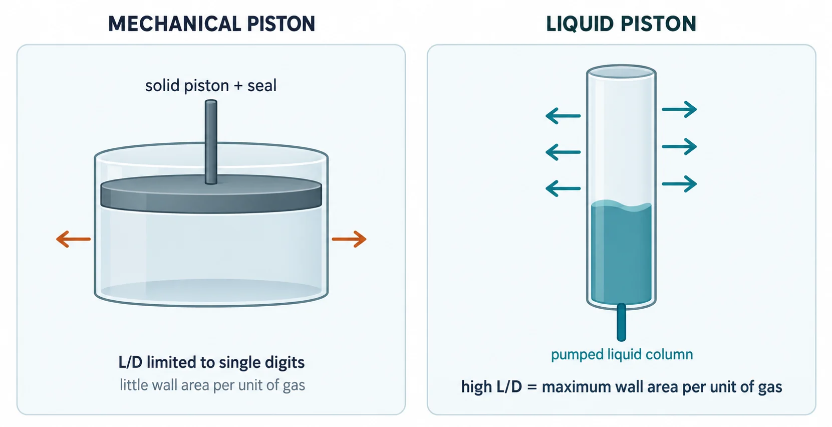
Both vessels below hold the same volume of gas. The tall thin one sheds heat far faster, because far more of the gas is close to a wall. Building that shape is what a mechanical piston cannot do and a liquid column can.
Four reasons liquid gets closer to isothermal
- 01
Geometry it can actually use
Heat transfer favors a long, thin tube: the more wall area per unit of contained gas, the faster heat escapes to ambient. A mechanical piston is realistically limited to single-digit length-to-diameter ratios — a long thin solid piston is not a practical machine. A column of liquid has no such constraint.
- 02
Speed you can tune mid-stroke
How fast the piston advances changes heat transfer twice over: it sets how long there is for heat to move, and it changes the gas flow patterns that carry heat to the wall. A mechanical piston must cycle quickly through short travel. A liquid piston can move far slower — and its speed can be varied during the cycle by controlling the pump delivery rate.
- 03
It conforms to any chamber shape
A solid piston needs a constant cross-section to seal against. Liquid does not. That frees the compression vessel to change shape along its length, which can be used deliberately to induce turbulence in the gas and drive heat into the wall faster and avoids precision machining.
- 04
The liquid is a second heat path
Beyond enabling the geometry, the liquid itself conducts heat away from the gas at the liquid–gas interface and out through the tube walls — a transfer route a solid piston does not provide.
What an installation actually looks like
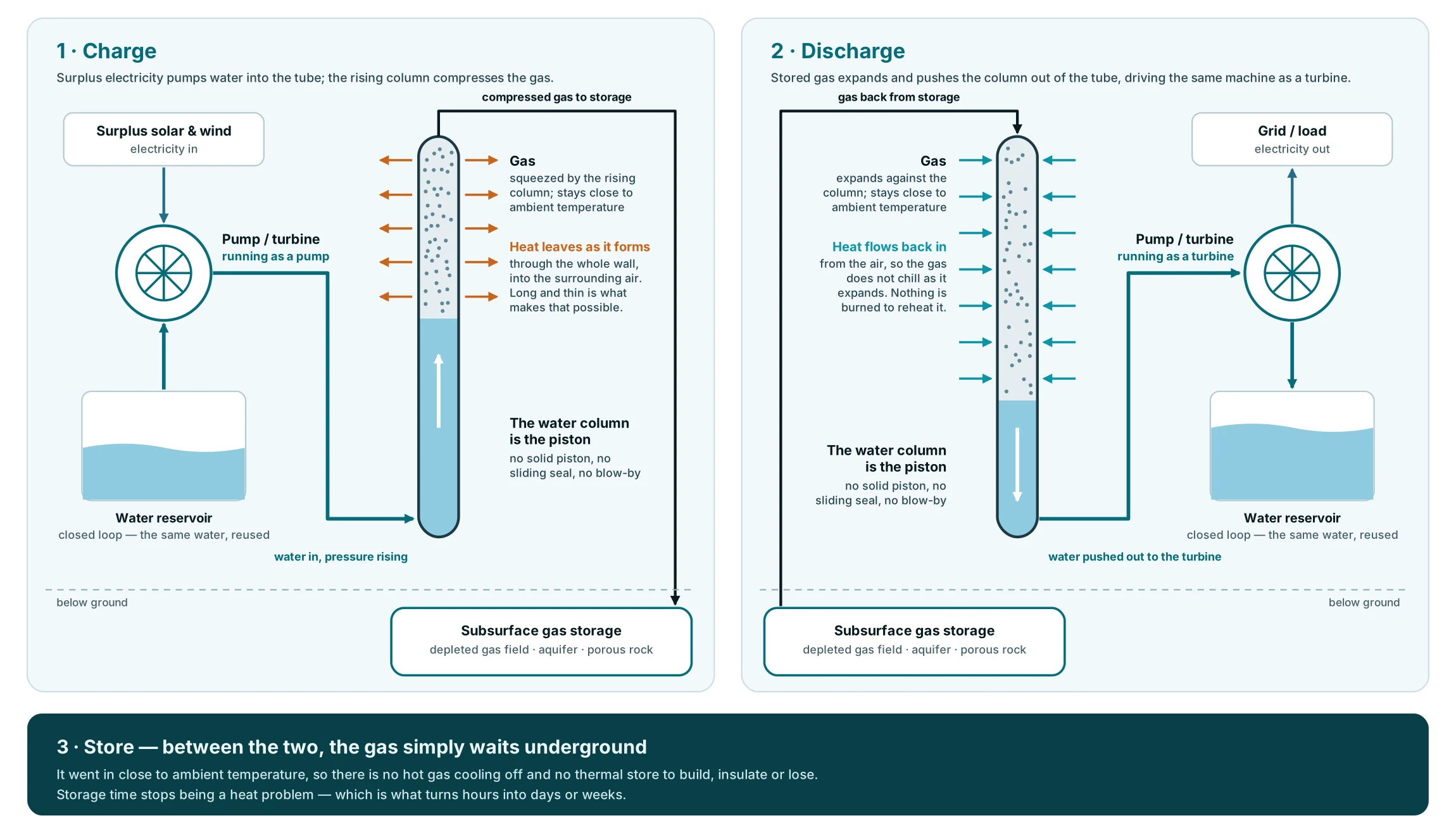
Pumps and hydraulic intensifiers flow water at increasing pressure into closed tubular compression vessels, raising the pressure of the trapped gas as its volume reduces. The components are variations of hydromechanical and electrical equipment in everyday industrial use — the innovation is in how they are assembled, not in inventing new machinery.
Three advantages that have nothing to do with heat
No sliding friction. A mechanical piston seals by pressing a sliding surface against the cylinder wall, and that friction is a continuous loss. A liquid column seals by being a liquid.
No blow-by. Gas escaping past the sealing surface is a standard loss term in mechanical compression. There is no sealing surface here for gas to slip past. Similarly there is no risk of oil exposure to the gas for critical applications like oxygen.
Pumping liquid beats compressing gas. This one is easy to overlook and may matter most. Raising the pressure of a liquid in a pump is inherently more efficient than raising the pressure of a gas in a conventional compressor: liquid's higher density means more of the motor's work is imparted to the fluid, and the sealing job is easier to begin with.
What it does not solve
A liquid piston is susceptible to gas dissolving into the liquid. How much depends on temperature, pressure and how miscible the two fluids are. There are established methods to mitigate it and these are incorporated into our design. Similarly, gas can be humidified during compression, however less energy is required to precipitate moisture at high pressure, adding to the potential savings.
Not a new idea but a measured one
19%
efficiency gain demonstrated for liquid piston compression over traditional gas compression
70%
round-trip efficiency shown to be achievable, removing a long-standing constraint on large-scale deployment
1906
earliest liquid piston work on record; later used in Stirling cycle applications
Humphrey, 1909
Liquid piston technology is not a laboratory curiosity and not a new invention. It dates to at least 1906, saw use in Stirling cycle applications, and then largely fell out of practice. The current resurgence is driven by compressed air energy storage — judged one of the few long duration approaches viable at genuinely large scale, and itself in existence since the early twentieth century. Two compressed air storage plants have run for many years; the basic principles and their effectiveness are well understood.
What has changed is the demand. Liquid pistons and near-isothermal compression now offer a path to adoption exactly as global demand for storage accelerates.
Three ways to handle the heat
Compressed air energy storage has run at grid scale since 1978. Every version of it has to answer the same question — what happens to the heat of compression — and the answer is what sets the achievable storage duration.
D-CAES
Let the heat go, then burn fuel
The original plants allowed the heat of compression to dissipate during underground storage, then burned natural gas to offset the cooling of expansion on the way out. Diabatic CAES works, but it is inefficient and carbon-intensive.
A-CAES
Capture the heat and store it
More recent approaches — Hydrostor, and Energy Dome using CO₂ — capture the heat of compression and re-use it to offset the low temperatures of expansion. It works, and it matters for both performance and equipment health. But storing thermal energy for long periods is costly and difficult, so the thermal store itself becomes the duration barrier.
I-CAES — EIC
Never concentrate the heat at all
Near-isothermal compression moves heat into the atmosphere as it forms, and passively draws it back during expansion. There is no thermal store to build, maintain or lose, because the atmosphere is the thermal store — and it is infinite in both directions. Duration stops being a thermal problem.
There is a second consequence. Because the process holds the gas near ambient temperature, what goes into storage is near-ambient too. Hot stored gas loses thermal energy over time, and with it pressure; near-ambient gas has far less to lose. Stored deep enough that the air and the surrounding earth sit at the same temperature, there is no thermal loss over time. That is what makes days-to-weeks duration a physical possibility rather than an engineering fight.
Why the economics work
Storing meaningful energy as compressed air needs large volumes, which is usually framed as a disadvantage. It is the opposite: those volumes come from naturally occurring subsurface features, so the marginal cost of the storage itself approaches zero.
$25/kWh
total capex per kilowatt-hour of energy storage, at the low end
$150/kWh
lithium-ion, for comparison — with roughly half the service life
2×
service life of batteries, with no toxicity, degradation or thermal runaway
The cost structure
On these figures: this is capex per kilowatt-hour of storage capacity, not levelized cost of energy. The two are related — storage cost is an input to LCOE — but they are not the same number and should not be compared directly against an LCOE figure.
The economics turn on a split that is easy to miss. Storage capacity is very cheap; power conversion is not. Spread the expensive conversion equipment across many hours of very cheap storage and the cost per unit of delivered energy falls sharply — which is precisely why the advantage grows with duration rather than shrinking.
Depleted natural gas fields are the strongest candidate: the geology is already mapped by the previous operator, the integrity is proven, and some of the access infrastructure can be re-purposed. Aquifers and other porous rock formations also work. Access cost is driven by depth, permeability and the shape of the formation — the last two determining how many bores are needed. At sufficient depth, higher pressures and geothermal transfer push round-trip efficiency up further, against some increase in up-front infrastructure cost.
Solution-mined salt beds are the most common storage mechanism but carry cost and complexity and are not available everywhere. For hard rock, EIC has partnered with EarthGrid, whose plasma boring technology, the company states, uses exhaust gas above 20,000 °C to thermally disassociate rock without contact or concussion, spalling off fragments that are continuously evacuated and can be re-used as a concrete additive. It is faster and cheaper than conventional drilling, which widens where subsurface storage is viable.
See the technology applied
The same technology underpins four very different industrial applications.